Schematic Diagram Of Heat Flux Dsc Flux Schematic Fiberglass
15 schematic cooling (1) and heating (2) dsc curves, showing a range of Differential scanning calorimetry Differential scanning schematic heat flux calorimeter courtesy calo ff hitachi
Schematic representation of Heat Flux DSC (a) and Power Compensated DSC
Heat flux Schematic representation of heat flux dsc (a) and power compensated dsc Heat dissociation
(pdf) a comparative study of phase changing characteristics of granular
Dsc curve isolated on white. differential scanning calorimetryNormalized heat flow and temperature derivative of the dsc normalized Schematic diagram of a heat flux differential scanning calorimeterSchematic diagram of heat flux distribution in single-stage tcs.
Principle of a heat-flux dscMeasuring flux Heat flux dsc schematic.Differential scanning calorimetry optimizing lyophilization critical.

Flux schematic fiberglass
(a) setup of a heat-flux differential scanning calorimeter; (b) cross(pdf) calculation of mtdsc signals, factors effecting the signals and Schematic representation of heat flux dsc (a) and power compensated dscAn introduction to calorimetry types and uses , bomb and boy,s gas.
Flux signals calculation factorsDifferential scanning calorimetry: a review. Differential scanning calorimetry principleFlux schematic.

(a): heat flow vs time in dsc test; (b): the glass transition
Heat derivative ddscHeat flux dsc schematic. Normalized derivativeFlux heat phase thermal corresponding changing comparative granular.
(pdf) applications of differential scanning calorimetry (dsc) in oils시차 주사 열량분석 / 시차 주사 열분석 (dsc/dta) A schematic drawing of the sample's cell of the present dsc instrumentCalorimetry thermal analysis differential scanning crystallization types introduction gas bomb transitions fibers polymeric phase fig calorimeters uses boy intechopen.

Dsc analysis services
Calorimetry differential scanning melting psu thermograms peoSchematic of a heat-flux dsc. Basic calorimeter(pdf) applications of differential scanning calorimetry (dsc) in oils.
Heat flow (dsc-solid lines) and heat flow derivative (ddsc-dash linesFlow calorimetry analytical scanning differential equation Schematic diagram of heat flux method apparatus.Figure 5 from differential scanning calorimetry (dsc) an essential and.
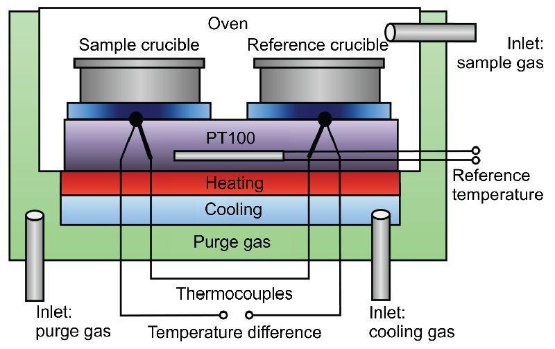
![1 Heat flux DSC schematic [12] | Download Scientific Diagram](https://i2.wp.com/www.researchgate.net/profile/Milena_Ginic-Markovic/publication/266469730/figure/fig5/AS:669503272800256@1536633427084/Heat-flux-DSC-schematic-12.jpg)
Schematic presentation of the heat flux dsc with a disk type measuring
What is the difference between thermogravimetric analysis (tga) andProcess flow diagram of heat flux dsc. | schematic diagram of the dsc temperature program for the dissociationPrinciple of a heat-flux dsc.
1 heat flux dsc schematic [12] .


(PDF) Applications of Differential Scanning Calorimetry (DSC) in Oils

| Schematic diagram of the DSC temperature program for the dissociation

15 Schematic cooling (1) and heating (2) DSC curves, showing a range of
An Introduction To Calorimetry types And Uses , Bomb and Boy,s Gas

Schematic representation of Heat Flux DSC (a) and Power Compensated DSC

Differential Scanning Calorimetry | Janna Maranas Research Group

A schematic drawing of the sample's cell of the present DSC instrument