Schematic Diagram Of Gas Turbine Engine Gas-turbine Engine
Fuel system turbine engine schematic apu aircraft systems requirements figure Gas turbine Steam turbine diagram
Gas Turbine Diagram
Turbine plant combined Water, steam and fuel gas flow diagram of steam power plant. Turbine gas engine energy combustion cycle engines pressure internal conversion britannica open used compressor exhaust wallpapers high machine velocity constant
Turbine gas cycle working principle power everything application
System boundaries for lcaGas turbine diagram Turbine diagram8 flow diagram of a simple gas turbine-steam turbine combined power.
Turbine sectional diagram[diagram] ge lm2500 gas turbine diagram Gas-turbine engineSteam turbine parts and components.

[view 40+] schematic diagram of wind turbine generator
[diagram] gas turbine jet engine schematic diagramGas turbine diagram [diagram] gas turbine compressor diagramGas flow steam turbine generating bpl modeling biomass.
Gas turbine cycle application: everything about gas turbine workingAll about general electric pg 9171 e gas turbine Turbine turbines turbin classification uap ge condensing components pelton impulse vapeur linquip difference shaft mesin fungsi[diagram] pv diagram gas turbine engine.

Engine jet turbine gas sketch station schematic nasa numbers gif aircraft engines parts number airplane modern location each military drawings
Turbine gas cycle plant power combined schematic system stock shutterstock vector generator steam engine compressor air find marine plants stuffSchematic diagram of a gas turbine engine. Simple gas turbine diagramGas turbine combined cycle power plant system schematic stock vector.
Turbine engine gas jet stages processing pngkitTurbine gas diagram engine energy education figure Aircraft systems: aircraft turbine engine fuel system requirementsGas turbine diagram.

Combined plants turbine gasification
Turbine gas types working principle components burner chemical engineeringSchematic diagram of a steam and gas turbine [5]. Inside a ge lm6000 (cf6-80c2) gas turbineGas turbine power plants: parts and functions.
Gas turbine diagram flow simple turbines electric cycle axial starting general support pg unit tutorialsDownload jet engine processing [diagram] gas turbine compressor process flow diagramBlock diagram of a simple gas turbine plant.

Cross-sectional view of the gas turbine generator
What is gas turbine power plant? working, diagram & applications[diagram] gas turbine propulsion systems diagram Schematic illustration of the proposed gas turbine engineTurbine lm6000 cf6 80c2 compressor pressure lpc.
Gas turbine engine schematicGas turbine working and types Gas turbine schematic and station numbers[diagram] gas turbine jet engine diagram.


Gas Turbine Schematic and Station Numbers
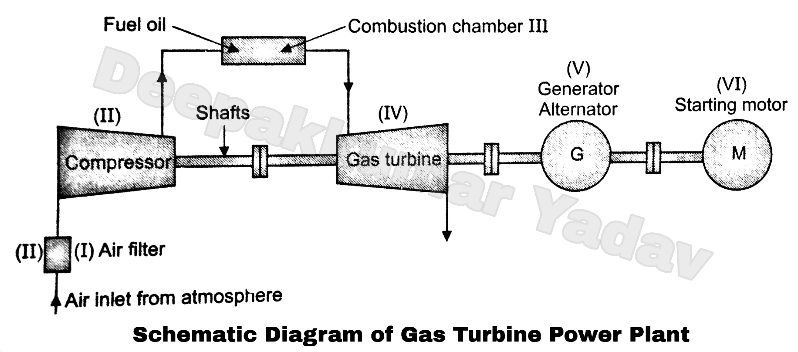
Block Diagram of a Simple Gas Turbine Plant

Gas Turbine Diagram
![[View 40+] Schematic Diagram Of Wind Turbine Generator](https://i2.wp.com/www.electrical4u.com/wp-content/uploads/What-is-the-Schematic-Diagram-of-Gas-Turbine-Power-Plant.png)
[View 40+] Schematic Diagram Of Wind Turbine Generator

Steam Turbine Diagram
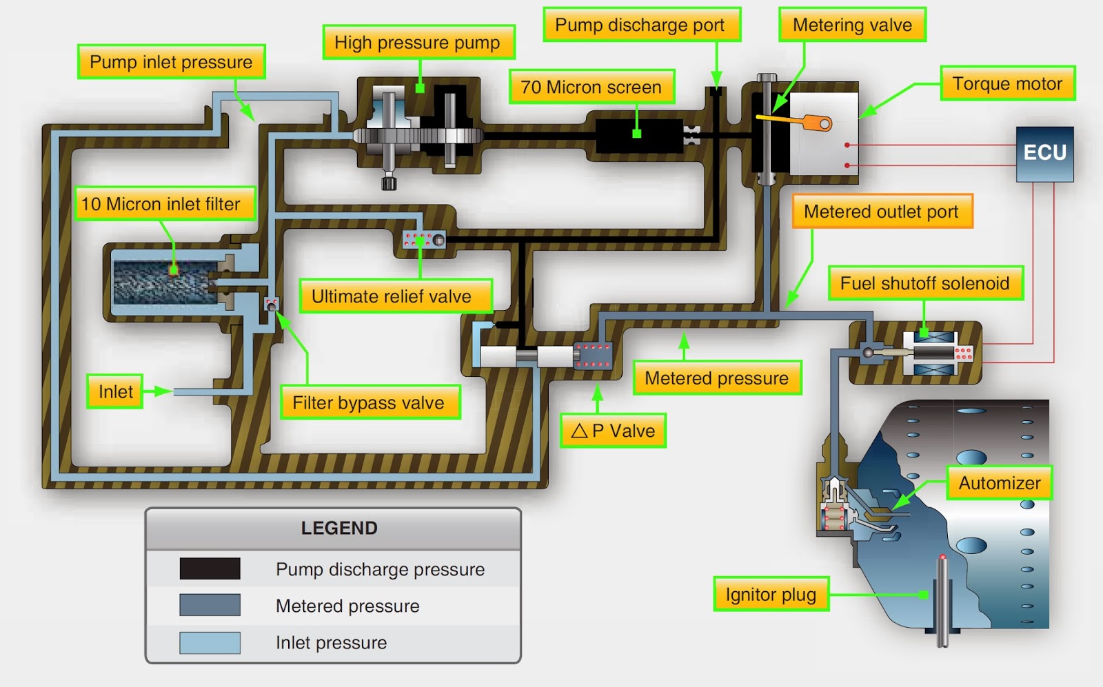
Aircraft Systems: Aircraft Turbine Engine Fuel System Requirements

Gas Turbine Diagram